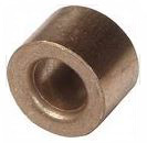
 Now that we are
beyond "thrust bearings 101", we can continue. For those with big dollars, you
can apply the Perkins system to your race engine. This adapter protects the
crank in a way that allows the
Now that we are
beyond "thrust bearings 101", we can continue. For those with big dollars, you
can apply the Perkins system to your race engine. This adapter protects the
crank in a way that allows the 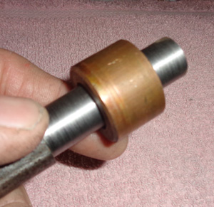 The tool we fabricated is simple to make on your lathe. Take a 3/4 bar stock
of solid mild steel and turn down the bar to the diameter of your pilot shaft,
less a few thousands to
The tool we fabricated is simple to make on your lathe. Take a 3/4 bar stock
of solid mild steel and turn down the bar to the diameter of your pilot shaft,
less a few thousands to 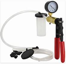 There is a very
nice tool that you can buy to help you "bleed" your racecar brakes and that
pesky clutch system. The clutch is probably the least desirable hydraulic
system on your racecar.
There is a very
nice tool that you can buy to help you "bleed" your racecar brakes and that
pesky clutch system. The clutch is probably the least desirable hydraulic
system on your racecar.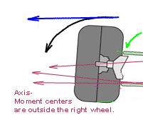 July 1st
update: Editor's note. After some experiments I have found that ROLL CENTER
AXIS POINTS (shown in the illustration below as RED and BLUE circles)
July 1st
update: Editor's note. After some experiments I have found that ROLL CENTER
AXIS POINTS (shown in the illustration below as RED and BLUE circles)
 The illustration shows you where
these lines intersect, but they are not static, so finding the exact location is where most racers
become frustrated.
The illustration shows you where
these lines intersect, but they are not static, so finding the exact location is where most racers
become frustrated. 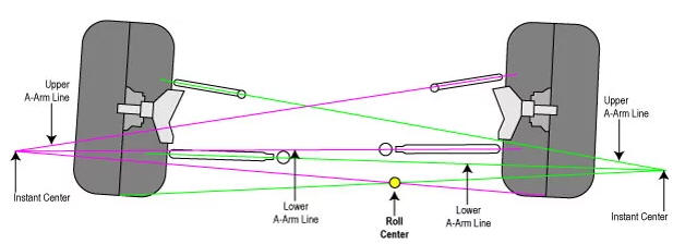
Reference: Search Internet for...
Roll Center, Roll Axis and Center of
Gravity.
Joe's Racing Products - Performance Trends
XYZ Input Chart -
Three Axis FAQ sheet
~~~~~~~~~~~~~~~~~~~~~~~~~~~~~~~~~~~~~~~~~~~~~~~~~~~~~~~~~~~~~~~~~~~~~~
Ballast from the
past...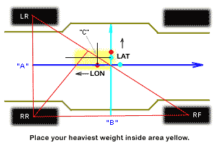
I bet you don't have bars located in your
Street Stock for this exercise...
In the early 90's (20th century) before a lot of you were born...the concept
of racing was "keep the car flat" and race the track. That is not the concept
today, Most guys like to
drive hard around the outside, but that is not
always the fastest way around. If everyone is racing "nose to tail" around
the top, the cushion will eventually break down. Consider
finding a better
way...
Most of you don't have bars located specifically for ballast. In the
illustration above the "yellow" highlight is where you place your
heaviest ballast. You want to balance the car and then remove/add ballast for
bite. Never add ballast at the corners for the sake of meeting weight.
Add your weight in the middle for your rules, balance the car and than add
weight where you need bite. If you need 40 pounds on the LR corner;
add
20 pounds over the LR, and remove 20 pounds from the middle (yellow zone).
This is like adding 40 over the LR. Your corners will change,
but your
mass should remain the same.
Ballast basics: Place the
heaviest weight as close to "center of gravity" as possible. In the
illustration above "area yellow".
The CoG is not physically located along
the chassis center-line. It is an average point located between two points.
The longitude CoG is a formula WB x FP [example (108)(.53.4)= LON]. The
latitude CoG is WT x LSP [example (66)(.52.2)= LAT].
Key: WB = wheelbase,
FP = front percent, WT = wheel track, LSP = left side percent, RSP = right
side percent.
LON = 58.32, LAT = 34.32 calculate for hypotenuse [CW], the
result would be 67.7. We must disect [C] with a line at 90 degrees.
There are basics that must be understood,
before you start set you car with tires and springs you plan to run on your
racecar.
Level out the car on your floor or pad and prepare to
scale the car.
Remove the driver,
remove most all your fuel, remove all "ballast from past" setups.
Your chassis should be void of any
ballast.
The car should be sitting ready to race, less driver and
any ballast-weight. Make sure your tire pressures are set properly.
If you
already know your normal ride height, make sure you have it set now adding
the height of your scales.
Let us begin:
As the car sits, nude
to the world, take a snapshot of your scales.
Make a note...how much does your
driver weigh??
The ultimate percentages for
a nude, 3000 pound stock car would be FP = 50, RP = 50, RSP = 50, LSP = 50.
That would give you 50% wedge.
Those numbers are crazy. But that is a
balanced racecar. However we
don't want that, we want some LSP, say 51.3%. This is why
we added our
doodads left of center when we built the car; the battery, seat and driver,
steering box and extra bars for ballast.
If we remove 100 pounds from RF
and 100 pounds from LR, the percents remain the same, but the wedge drops to
54%.
The car remains balanced. Now if we take 50 pounds from the RR what
happens? Yes the wedge goes up but the front increases as well.
Look at
your base "nude-mass-total". Subtract that from your weight-rule. Example
3000 pounds EOR minus your "nude mass" (2675) = 325 pounds.
Place your
heaviest ballast as close to COG as possible. As you add ballast the LON and
LAT will move because your racecar is dynamic not static weight.
Let us
say you add 100 pounds at CoG (25 pounds at each corner). Your percentages should
not change. If it did, adjust the location away from the highest corner.
Move the CoG ballast L-R or F-R in order to maintain ballance on four
corners. This ballast can be raised when needed to access more "roll-axis" if
needed.
Now consider your driver and place him in the car. Say 185 pounds on the
left (92.5 pounds LR-LF). The LS weight should increase percentage.
Your
cross weight should be 53% or higher and 53% should be on the left side. Not
bad at all. But you are not at weight. Now you need to add more weight.
But before you do, you must find CGH or center-gravity-height. I have a link
here for you to follow, but I can save you some time, your CGH for a metric
stock
car averaging 3000 pounds will be close to 22 inches, with rear of
car lifted 8 inches from ground. Here is the link:
http://www.longacreracing.com
You are still 115 pounds shy, so
carefully add weight increasing it to the rear. Again keep this ballast as
close to CoG as possible while stacking along the line of CGH.
This is the fundamental moment arm where
ballast (mass) in a physical third dimension is placed in motion by
centrifugal forces. If this mass is placed too far from the CoG
the
dynamics are slowed and the reaction is sluggish, requiring far greater
forces to create action, thus the reactions are just as sluggish. If this
mass is placed too high
above the CGH, the centrufugal forces are
dramatically increased and all actions become uncontrollable, lifting wheels
off the ground and forcing weight over the nose.
Remember I
said the CoG will move, it is dynamic. You can adjust dynamic CoG movement
with spring weight, and tire pressure, use your weight jacks and reset the
ride height.
Your shocks and springs control the four corner dymanics. If
the car is balanced these adjustments, even subtle ones can improve handling
in almost biblical proportion.
My suggested
percentage balance, before you take a single lap: FRONT = 50%, REAR =
50%, LEFT SIDE 53%, RIGHT SIDE 47% with a CROSS WEDGE of 53%.
Go take some
laps and make your adjustments. If all fails come back to this setup and
start over...you get it right, you will be fast!!
I gaurantee it.
Simple ballast adjustments:
The
basic of ballast is to meet your track rule at the EOR (end of race).
This is your primary objective. So start by placing as much of the needed
weight as close to CoG
as possible (yellow zone). Now look at your corner
weights on the scale. If all is correct you should be close to balance.
Adjust your weight jacks as required to meet a good
balance point. Keep
your ride height consistent around the car. You will have a hard time
maintaining 50% all around, but "what the hell" try it and see what you get.
I did pretty good on my first shot, I managed 50% front and rear, but
lost my "cross" percentage. That I can get back very easily. You should
keep in mind "negative wedge"
is a pavement thing, you are running on
dirt, you are looking for "side bite" and "forward bite".
That comes with RIGHT SIDE
percentage and REAR percentage.
If you want more cross, remove weight off
the Left Front or add to the LEFT REAR. You want less cross, remove weight off the Left Rear or add
to the Left Front.
The tricks are endless...but you must maintain the MASS
while doing this exercise. In other words "do not
ever add weight for the sake of
percentage"!! Maintain your basic
chassis weight with driver. Add
weight in order to tune the car "properly". Properly means you tune so the
car can be run anywhere on the track. If you need 50 pounds on
a specific corner
in order to run faster on the bottom, remove 25 pounds from CoG and add that where it is needed...the result will be the same.
Example: Need more cross - add 50 to the LR
and 50 to the RR, now remove 100 off the LF. You have more CROSS and more
REAR percentage.
You have increased RIGHT SIDE BITE,
the chassis MASS
remains the same. Now finish the job by increasing the RIGHT
SIDE percentage without increasing mass.
Something
must go on a diet...
In the grand scheme of things setting up your racecar is a very tedious task.
Let me state that differently,
setting up your racecar to run anywhere on the track, now
that is a
tedious task. It is not hard to make a racecar rotate. Place a lot of ballast
behind the fuel cell and stand on the gas. Any kid with a third grade
education can
figure that one out. The problem is, that kind of setup, the
racecar runs one line, one groove and without a cushion the driver will be
"cheek-pinching" the entire event.
Anytime I see some guy with big hunks
of ballast hanging off the rear of the car, I see 2 or 3 inches of stagger. I
know exactly where he is going to run. My driver will take
full advantage
of that. I also notice the racecar that tends to sit, with the driver side at
more than 55% left side weight. Take a good look at the racecar with a lot of
right side lean while sitting static. What does this tell you??
Basically that the driver is a
heavyweight. But if not, you can expect the car will be sliding
sideways, not
rotating as expected with little counter steer as well.
This car will bounce into the apex and there is no way to be sure the car is
under control.
So where is the best balance?? Most dirt racecars
have a relatively high cross weight, close to 53%, and that will support
OVERSTEER. You want OVERSTEER, but you
want to control it. If you have
these numbers F-48%-R-52% and X-53%, you have a very raceable car. But in
order to get these numbers with a "leaner" left
side, percentage that can
be a real problem. The LH percent should not be so high that you consume all
of your "roll axis" energy moving the weight left to right. Consider
the
"two by four"...a short piece will weigh the same laid either side on the
scale, but laid on the short side, the roll-axis is augumented in your favor.
I mean, ballast
adjustments are less exagerated and simple aletrations on
corners can be made without adding weight. The "upright theroy" (ballast at
CGH) offers preeminent weight control.
Think of it this way. If you
want to run up on the top you don't need as much RIGHT SIDE bite to complete
the apex. But the same car entering at the same velocity into
a bottom
groove, you will need more RIGHT SIDE bite. At 55% left side you must apply
more left to right "roll axis", and it must be applied sooner and harder at
turn entry.
That can't happen because the heavier your LEFT SIDE weight
is, the more "sluggish" it becomes to roll the weight, especially if you have
some extreme step in the car.
Take a moment and look at
SuperCalc...
Tip: Set the car to 50% LEFT
before placing the driver in the car. Do this with 48% on the front. Now add
the driver, read the scales. Now add right side weight to the
right of
your CoG. As you increase right percantage you will increase cross as well.
Try to keep your L-R percent close to 2% difference. It can be done.
~~~~~~~~~~~~~~~~~~~~~~~~~~~~~~~~~~~~~~~~~~~~~~~~~~~~~~~~~~~~~~~~~~~~~~~~~~~~~
Nine Inch Tips...
The pinion bearings. When changing the pinion bearings, or adding a new set
of gears to your rearend, keep in mind the pattern is easiest to complete if
the pinion is
properly set up first. In racing you should always be sure
the bearings are not worn this eliminates heat and heat is a problem in
racing rears. The biggest issue is that
spacer that sits in between the
front and rear pinion bearings. In the stock setup this was a "crush spacer".
When heat is generated in the rear-end the "crush spacer"
collapses and
allows for bearing growth. This generates a problem because this can lead to
pinion failure if the washer collapses too far.
The most common fix is
the solid pinion spacer and shims that allow you to preload the bearings for
proper fit. This was a solid spacer, but the problem was obvious.
The
spacer is sloppy on the pinion and the shims can easily be crushed or torn
apart if the bearings over-grow due to excessive heat. These spacers will
fail. QP Performance
sells a unique piniion spacver kit for 15 bucks that
is a 2 piece design that allows the shims to be installed between the spacer sections. One end of the spacer is
tapered to seat
the rear bearing cone, while the other is flat to ride
the rear of the front bearing. Set this up by pressing on the front bearing
while leaving .005 end play. Use a dial indicator at
the rear of the
pinioon and check run-out. Now install the yoke. Using your impact drive the
yoke on. Now check preload by testing the amount of "inch-pounds" it requires
to turn
the pinion with seal in place. This is done before placing in the
housing. You should read 7 to 10 inch pounds to turn the pinion. I tested
this theroy by placing the pinion in the freezer
over night, the
inch-pound test delivered 3 to 5 inch-pounds to turn the pinion. This preload
is important if you want the rear end to last a season or two.
Inserting
the pinion is a simple task and you should have a decent pattern out of the
box. If not, you can adjust the SPACER SHIMS or use pinion "position" shims to move the pinion forward.
Check your pattern to be sure it is not too tight (see illustration). As a
rule, I adjust the
carrier locks for about 10 thousand back-lash.
I might suggest
placing your
back-side on a diet. If you are running modified stock or sportsman stock,
you might want to replace that Ford ring gear carrier with a lightweight full
spool.
QP Performance sells a nice unit that does not cost an arm and a
leg. These are way easier to setup and you will notice a big loss of
"axle-turning-fat" immediately. On a side
note...
You guys in this class...stop using those junk-steel Chinese mini-spools
(period)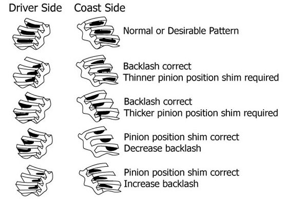
The normal pattern is what you look
for. Anything else will end up as a disaster.
(Illustration credit: unknown)
~~~~~~~~~~~~~~~~~~~~~~~~~~~~~~~~~~~~~~~~~~~~~~~~~~~~~~~~~~~~~~~~~~~~~~~~~~~~~~~~~~~~~~~~~~~~~~~~~~~~~~~~~
SuperCalc - My spreadhset for street-stock
racecar on clay tracks. (Church-Rule: 48/52/54)
Back in the days
of CPM operating system there was a spreadsheet known as SuperCalc. The
spreadsheet application of today is Microsoft Excel, but in memory
of my
favorite I have borrowed the name for just a few moments. I hold no claim to
Supercalc, but this spreadsheet and the web pages that are referred to will
come in handy at your race shop.
You can open the spreadsheet here:
MyCalculator
(click to download)

You will need a spreadsheet application
that can open .XLS files.
After you open the sheet, you can enter your
scale data and follow along here...
You enter your data overtop mine. My
car is the default weight settings for my 3200 pound Street Stock.
Use
the BLUE cells and enter scale data. Next enter the desired WEDGE, target
percentage you wish to reach. 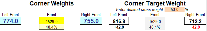
The calculator
will advise you of negative and positive corners and give you the best result
for RF/LR corner weight.
In most cases you will only be rerquired to add a
few turns into the LR corner. You will remove turns if the WEDGE is to high.
The Ride Height portion is a database. WHen you scale, check your ride
heights and enter the data here. When you save the sheet
for later use,
those ride heights will be posted for your calculations. You can add notes
here as well. Use this as a simple weekly Database.
The Center of Gravity
Height calculator is a must.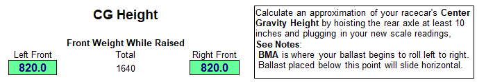
Most street stock
racers have no clue where the CGH is at let alone the Center of Gravity. This
calculator not only displays the
CGH, it will also calculate your Ballast
Moment Point (BMP) The BMP can be very useful when raising ballast in your
car.
Your Center of Gravity is simply the front/rear weight percentage
subtracted from the wheel base. In other terms, a 50% front weight
would
have your CoG located one half the distance along the wheelbase from front or
rear. If you have 52% on the front, you have 48% on the rear.
The CoG will
be located further from the rear axle than the front.
Example: 108 X .52 or 56.16 inches measured
from the rear to front.
Now the spread sheet, when calculated
will offer you a location above your floor where the ballast in your car
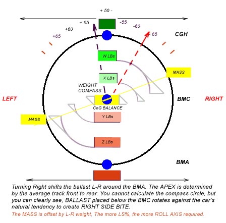
begins to work. This calculation is at CoG only.
So this is where you
place your heaviest ballast block. Adding smaller amounts to the right of the
CoG will increase the BMP roll axis, to the left will decrease roll.
What
must be understood...positive wedge is OVERSTEER, you must counter-steer to
keep the ballast under control. Proper control of the ballast allows the
mass to force more load weight (bite) onto the tire patch. Turning the
car, you must use as much tire as possible without over rolling the mass onto
the side wall.
Note: If the tire rolls
beyond your groove pattern, you can groove a tire like Rembrandt all day long
in the shop, it will be worthless on
the track.
There are no
perfect spreadsheets, no absolute websites for dirt racing, what must be
understood is balance. You cannot win on dirt if the car is less than 50%
cross.
Oversteer is loose, and loose is fast (period)
To finalize...CGH
is that point where added ballast can roll the car onto its side. Like
the mast on a sail boat, without the keel, the mast weight alone will tip the
hull over.
The BMP is where you would attach the mainsail boom. Enter a
set of Go Kart numbers 50 inch WB, 5.5 inch ride height and raise the rear to
15 inches with 50 pounds at L/R front corners.
There is no way a Go Kart should
ever roll over. The Go Kart CGH is a negative number!!
I hope this
helps. You must understand balance and counter-balance. Mounting a set of new
tires everyweek in order to win 300 bucks and a trophy, this ain't
grass-roots. If you can afford to scrub away new tires, have at it.
But if you want 3 or 4 nights out of that investment, may I suggest you learn
racecar balance, proper amounts of oversteer and counter-steer.
Note: You can apply the same train of thought
by using the CGH calculator along the left side of your chassis. Take the
average wheel track front to back and raise the left side of the car by five
inches (your side roll factor). Read the RIGHT SIDE scales. Do you see
anything that might change your mind about CGH?? Wait,
before you lower that jack,
watch the scales and crank 1 full turn into your RIGHT REAR SPRING...
I have added a
Corner Balance Calculator
available here. This can be used on your phone as well.
This calculator requires your scale numbers
and allows you to adjust mathamatics for percentage cross weight (balanced
car).
![]()
This calculator displays approximate "side bite" based upon your cross-weight
percentage.
The ON-LINE version uses my scale data less my driver and
fuel. You can change these inputs and recalculate for your corners.
To
clear the form, simply "refresh" the page
(CTRL+R).
73's Robbie K9OJ from Terry W3GAS
The identical theroy can be applied front to back, but because the
wheel base is so long the CGH would be very high above the chassis.
Balancing chassis "dive" is done with springs,
shocks and tire pressure. What must be presented in this argument is over
implementing these actions
can lead to a severe front end push simply
because the engine is the heaviest mass in the car. Adjust your racecar to achieve
the maximum
right side bite and forward bite. Doing so the RIGHT REAR
wheel does the heavy work.
Tire temperatures should be monitored after every event.
Note: The
wider the chassis at the points of MASS the higher the CGH must be, for the
greatest balance, some level of compromise must be met.
~~~~~~~~~~~~~~~~~~~~~~~~~~~~~~~~~~~~~~~~~~~~~~~~~~~~~~~~~~~~~~~~~~~~~~~~~~~~~~~
The
Forgotten Myths of Racing:
The most abused information "never thought about" by dirt stock-car racers
are...The Roll Axis Center, the
Center of Gravity Height and
Tire Heat Cycles.
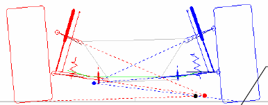
Roll Axis explained in simple terms
here and all you need is a ruler and a plum-bob. You should never head-off to
the track without this information.
To determine your Roll AXis Center,
use two sheets of standard letter size graph paper, rotate
them landscape and lay them flat, side by side. Now
on the right side sheet,
enter these graph marks. The height from shop floor to upper ball joint.
Define a line for the floor and count up the number of blocks
required for
this measurement. Now find the height from the floor to the
front pivot point
of your
upper control arm. Mark this block. Draw a line between the
two marks. Now
do the same for the
lower ball joint
and the lower control arm
front pivot point
on the
frame. Draw a line between these two marks. Do the
same for the left side
sheet. You should have four marks and two lines on each side. Extend these
lines across the paper until they dissect each other at the
"instant
center". Do this for both sides. Now locate your "tire contact patch" on the
floor and measure that distance from the
king pin incline
which passes
through the upper and lower ball joints. Mark these on your graph. Now
draw a line from the contact patch through the "instant center". Do this for both
sides.
Where these lines dissect, this is your "roll axis center". For a
dirt racecar, you want this point to be left of center as you face the car.
The higher above
ground the more the chassis will roll into the turn. To
change the ROLL CENTER you adjust the upper control arm pivot points (up or
down). You can also
change the ROLL CENTER by changing wheel offset (see
illustration below).
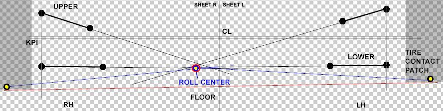
The ROLL CENTER
graph allows you to imagine a theoretical point around which the chassis
rolls.
For more information.
FYI: The
rear end of the car also has a ROLL CENTER it is located just below the third
member. In a Street Stock configuration, there is limited adjustment.
Center of Gravity Height is
another myth. This one requires you to be on your scales and prepared to
raise the rear of the vehicle.
Tire Heat Cycles are often
forgotten entirely. Especially for those of us who are limited by feeble
budget to purchase new tires every week. For the "fat
wallet" racers,
tires are a commodity. For many of us tires are an expense we must adjust for
if we want to be competitive. We are often forced into buying
used tires
in order to compete every week.
One thing we can do to prolong the life
of a race tire is to start with a "first time" heat cycle. This allows the
rubber compound to form more consistent.
In a race shop we take a basic
"block" tire and groove it for the "corner application". Once this is done
some racers wrap the tires in a wrap, while others
allow them to sun
bathe for a few hours and then slow cool them down. This is the "easy cycle".
This means we bring the tire up in temperature and let
them cool without
agressive race wear and tear applied.
That is really all you are doing to
the tire and it can be done in a "home brew" oven. You will need a wooden box
that can hold your tire in place. The tire
should be allowed to rotate
slowly in a circle. There will be an opening in the box that allows you to
place two sun-lamps facing the tread of the tire and
located about 5
inches from the tire tread. Now allow the tire to heat up to temperature
slowly. Through a small opening on the opposiong side from the
lamps, use
your infrared thermometer and check the tire until it reaches about 135-140
degrees at the surface. Turn off the lamps and allow the tire to cool
naturally. This cycle process does improve tire life and the project to build
a "first cycle box" will cost you a lot less than a single tire.
Keep in mind...for every 10
degrees of tire temperature, the tire increases 1 PSI.
~~~~~~~~~~~~~~~~~~~~~~~~~~~~~~~~~~~~~~~~~~~~~~~~~~~~~~~~~~~~~~~~~~~~~~~~~~~~~~~
Off site calculators:
Spring rate calculator: You will need the corner weight, the unsprung
weight (front and rear) and your lower control arm dimensions.
Let me
help. If you click the link above (in red) you will open a page at
www.RideTech.com.
I have attempted to duplicate their formulas but I have had some errors
that I cannot seem to track down. Perhaps that is bacause I am applying the
math
to Street Stock and Pure Stock with separate coil and shock GM front
suspension. Click the link and take a look at the page:
Step One
Sprung Weight. That will be your scaled weight as read from your scales.
Let us use 750 pounds on the right front. In Step One we must
also enter
the un-sprung weight. For a Street Stock with a GM clip that would be close
to 95 pounds, less for 8 inch wheels; Sprung Weight would be 655 pounds.
Now we calculate the Motion Ratio. Step Two can be tough to calculate
for a stock car because this calculator is using "coil-over" technology for
this formula.
Dimension A is the lower control arm measured from frame
pivot (mounting bolt) to the base of the shock mount. Dimension B is measured
from the pivot
to the center of the lower ball joint. This does not offer
us a real motion ratio because many of us use offset wheels and that effects
the Motion Ratio
dramatically. Another factor is the spring location. For
a stock GM lower control arm, the spring is located about 8.325 inches from
the frame pivot.
In most cases input result will be .3XX to .4XX Motion
Ratio. If you measure from frame pivot to the center of tire (perhaps 21 - 23
inches)
the ratio becomes lower.
The Coil Spring Angle is Step
Three. For a GM clip Street or Pure Stock this angle is 80 degrees. The
GM metric design is perfect for racing applications
in as much as the
spring angle is less than 90 degrees. The weight applied during cornering
pushes down and slightly away which improves applied angle
pressure to the
tires...this increases side bite.
The Shock Stroke or Step Four.
This entry is determined by your track or sanction rules for your class. If
your shocks must be in stock location you can only
enter an 8 inch
setting. This is because the shock location for a GM clip is in between the
upper and lower control arms. You are limited in your shock travel.
If
you are allowed to use adjustable weight jack screws (non-pocket spacers) you
must mount your shock forward of the spring. This allows you to use long
stroke shocks. But even so, the spring will be limited to 10 inches. In this
case you can use a 4 to 5 inch stroke. Most front springs have a bind factor.
You can
determine that factor by measuring the coil diameter and
multiplying it by the number of coils (0.875 wire diameter times 5 active
coils = a 4.375 spring travel).
I suggest you enter a 4.1 stroke if your
shocks are 9 inch. This allows your shock to travel a proper ratio to your
spring's active travel.
Step Five is the result of the calculator. The
Racing spring requirement is a good starting point, but
you must determine your needs
for track conditions, banking,
chassis design, roll axis, tire size and
driving skill. May I suggest you review this
link:
![]()
Corner Balance
Calculator: You will need a snap shot of your scale results (corner
weights).
![]()
~~~~~~~~~~~~~~~~~~~~~~~~~~~~~~~~~~~~~~~~~~~~~~~~~~~~~~~~~~~~~~~~~~~~~~~~~~~~~~~~
Fuel Pump Indexing:
This is no big deal if you have your engine man on site. He will know what to
do, but lets take a quick look inside. Just for the record you might learn
something.
Most Street Stock and Sportsman racers are running a GM Metric
chassis. Most are running some form of small block Chevrolet power plant. It
could be a "crate"
motor or an "open" motor, but in most all cases it is
not located in OEM stock location unless the rules are very strict. Most
rules allow a setback and the forward
left hand spark plug location
dictates the setback. Also, for you novice racers, lowering the engine is one
trick that offers better control of your roll center. Setting
the engine
down and back will render a far more nimble racecar and increase front
suspension handling dramatically.
Doing this demands modification to your
engine cross member. You will have to relocate engine mounts, but this is a
racecar and you won't be using stock rubber
engine mounts, so don't panic.
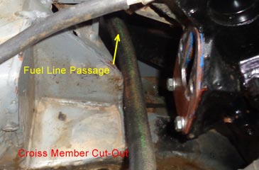
You will have to cut out a reasonable portion of your cross-member on the
right front side in order to allow clearance for your fuel
pump. This is
what I am getting into here...in order to run fuel lines, you will need to
"index" your fuel pump.
Let me detail this for you. Lowering the engine
and setting it back will require a cut into the cross-member. You will then
"box" in that cutout in order to add strength
to the member. See the
picture below. This is a stock cross member. The engine mounts are very
simple to build and the steel brackets that bolt the engine in place
are
off shelf items at most any speed shop.
However the problem is going to be
your fuel pump. In some cases you won't be able to use a stock pump,
but this is racing and you don't really wany to run those
3/8 inch lines
anyway, so prepare to buy a decent fuel pump with 1/2 inch NPT inlet and
outlet for AN type fittings. Use a 10 for the inlet and an 8 for the outlet.
Depending on your fuel system and cubic inches, you will purchase a 10 or
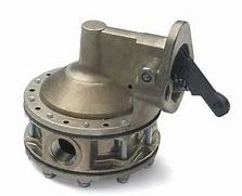
a 15 PSI pump with a minimum of 110 GPH. See
the Carter Pump shown below.
Now for the real down to ground
substance of this article. You
may need to index the fuel pump. Do not purchase a pump that cannot be
indexed (clocked). If you
are not sure, ask your vendor to explain.
Indexing means you can adjust the pump inlet and outlet fitting locations so
the lines can be routed through your cross
member after modifications. In
the image below, the lines are passed along the block from the underside of
the chassis and connect to the inlet located at the rear
of the pump head.
The outlet is directly piped up to the regulator which is located directly in
front of the carburetor. The shorter
these lines the better.
So what to do about indexing??
Well, you purchaszed a fuel pump with several screws (8 or 10) of them along
the lower half of the pump body. You will have to remove
these screws. The
pump probably has the inlet and the outlet faced front to rear inline. If you
must index (clock) one port or the other you must insure it does not create
a different issue for the opposing port. The number of screws dictates the
degree of your rotation. A ten screw pump is 36
degrees per screw. The eight screw units afford
a 45 degree index per screw. Why do I
say per screw?? Because you are going to rotate the entire upper section,
including the diaphragm by as many screw holes as needed
in order to index the pump
ports properly. The diaphragm
may have the same number of holes or twice as many. If it has twice as many
holes you can index by half as much.
That means a ten screw 36 degree
index can be reduced to 18 degrees by using the next available hole. Otherwise you are
limited to 36, or 45 degrees of rotation. Do not
force the diaphgram into the next hole. Rotate (clock) the pump body
only!
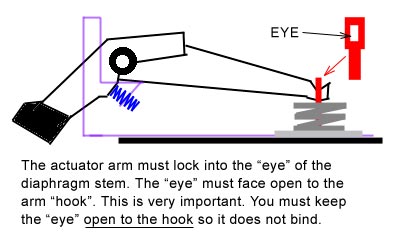
Above you
see is the Carter fuel pump and a crude illustration of the actuating arm
that adresses the pump motion. This is a simple rocker arm lever that is driven
from
the fuel pump push-rod that rides on the camshaft lobe directly
behind the timing gear. This is the first lobe on the cam. It drives the arm up
and down while the arm
pumps the diaphragm which draws fuel in then pumps
it out. A very simple mechanical pump and not much has changed for over 75 years. However, indexing is not
something we do with stock single stage
pumps. In racing we run triple stage or higher in order to deliver as much
GPH (gallons per hour) through the system as possible.
Now the
details...if you must rotate the pump in order to index it properly you must
not force the diaphragm main shaft off pitch. This is done by over clocking
the body
rotation by just one hole. Incorrect alignment can happen and the results are
catastrophic. Note the arm above, it is designed like an anchor hook
that lifts the stem of
the diaphragm shaft up and down.
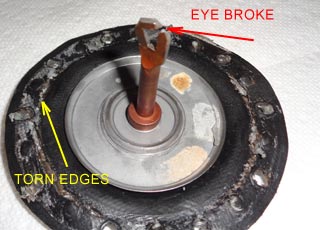
The eye of the
stem must line up facing the hook. Like threading a needle, the hook must
pass through the eye with no bind on side.
If there is a twist in the
stem it will bind with the hook until it wears the hook away and the hook
breaks off or the eye breaks open. The twist also provokes the diaphragm
itself and causes premature failure. The rubber diaphragm will rub along
the surface of the lower pump chamber and form small tears along the edge. It
will decline and the first
notice will be the fuel pressure is bouncing, as
much as a pound, prior to failure.
The best way
to index is to remove the actuator pin, the actuator arm and the actuator
spring (blue). Carefully remove these and set aside for reinstallation later.
Now
carefully remove the 8 or 10 screws from the body. Leave two opposing
screws in the body and remove them last. This technique will separate the two pump
bodies.
The diaphragm spring will
gently force the pump apart. This method insures you will not tear the
diaphgram along the seam. Now rotate the lower portion of the body so the
inlet and outlet are indexed properly to fit your configuration. These
inlet and outlets are lined up front to back so the front outlet must be
facing the radiator. You will most
likely rotate the diaphragm 20 or 40
degrees. My Carter pump rotates 45 degrees and I use a 45 degree 10AN fitting
to angle the line back under the motor mount. This works
perfectly and it
protects fuel lines from track debris. However, I had to rotate the diaphragm one
screw position and re-align the shaft eye so the actuator was open facing the
anchor hook. I then reinstalled the pin and the spring. I tightened
two screws and tested the pump by hand. Satisfied that the pump actuator was
correctly aligned I finished
the install.
FYI: Don't waste your time trying to attach a diaphragm spring shaft to the
anchor hook without removing the actuator. You will frustrate yourself into a
panic.
In the images below you see what a misaligned actuator can
do. Note the damage to the shaft,
the diaphragm and the anchor hook. This all happened inside 200 laps of
racing. 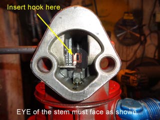
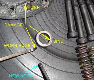
Don't make this mistake. If you must index your
pump make certain the actuator and the anchor hook are aligned properly. It
may cost you a win, a DNF or much worse.
Keep in mind that there
are different spring lengths and compression for actuator arm and the
diaphragm spring. These depend on PSI at the regulator. Too soft, the fuel
PSI
will bounce, too hard the pump flow will be decreased and the pressure
on the shaft eye will exceed specifications.
The diaphragm stem (shaft) can be rotated a
few degrees.
Be wise...on an 800 CFM
Holley, set the PSI to 9 pounds max. Note: I replaced this pump
with a new one. I selected a Quick Fuel 130 GPH replacement.
Do
not purchase this brand of pump. Yes, it looks pretty but it is simply
a polished turd. Buy the Carter or Holley version of
indexable SBC fuel pump.
~~~~~~~~~~~~~~~~~~~~~~~~~~~~~~~~~~~~~~~~~~~~~~~~~~~~~~~~~~~~