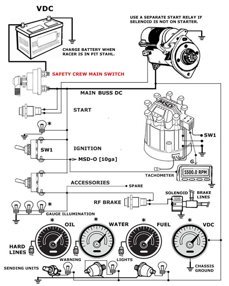
Stock Car basic wiring...this is a basic schematic used by Church.
The basic wiring disgram displayed here can be applied to any stock car
you are building.
The battery is your source of power, it may be 12 or 16 VDC depending on
your starter motor requirements. You must remember that 16 VDC can be too
high for some panel indicators and certain accessories so be aware of your
equipment. Panel lamps and "light emitting diodes" are critical because
higher
voltage limits their longevity.
You do not normally charge a "grass roots racing" stock car while on the
track.
Your race times are limited to a few miles so charging circuits are not
required.
However, if your rules require an alternator be installed, use a single
wire system
and wire the alternator output directly to the battery positive terminal.
Always charge your battery when in the pits...
The starter curcuit shown applies to a solenoid that is located on the
start motor.
If you do not have this setup, you must use a Ford type starter relay
mounted in
or near your engine compartment.
Likewise, the MSD shown here uses an HEI style distributor common to GM
systems.
You can use this setup or add one of the AL series spark boxes inside your
car and
wire to the distributor and tachometer as required. All MSD wiring
diagrams are
available on-line.
Note that I use two separate switches for ignition and accessories. You
can add a
third switch and separate out your accessories. Keep your MSD/tach/AL6 on
the same
ignition switch. Run your accessories, gauge illumination, brake control
and cooling
fan from additional switches. Turn off accessories during caution periods
to concerve
your battery power. If you use an alternator, this conservation is not
required.
Keep in mind, LED indicators save on battery drain. Items like your MSD,
fuel pumps,
relays and incandescent lamps, they suck up the most battery charge. You
normally
"do not remove" your battery charger until you start your engine
Electronic gauges: These are your best bet in a racing situation. They do
not require
physical lines from your engine. Electronic sending units are simple to
wire and the
gauges require less physical size. However, there is a draw back...many of
these
e-gauge systems do not offer warning indicators.
In the system shown we apply mechanical sending units along with "hard
line" gauge
operation. The pressure gauges are connected with steel braided lines to
the engine.
The temperature uses capillary tube. You must use caution when installing
the gauge...
any strain on the tubing is not recommended. Oil pressure sending units
are available in
many types, we recommend using a sending unit that can control the
ignition when the
oil pressure drops below 10/20 PSI. These units can be connected to a
warning system that
reminds the driver when oil pressure is low. It can also shut down the
engine when pressure fails. Note: Losing a bearing is one thing,
destroying the crankshaft is catastrophic.
You can select just about any gauge manufacturer you choose, but keep in
mind that
racing is tough on equipment. Gauges with oil filled displays take a
beating and
the indicators are likely to be more accurate. The "quick glance" method
of
installation places all the indicators at 90 degrees, this way a "quick
glance" tells
the driver all is "Ok"...all indicators are at 12 o'clock.
In my opinion, the four gauge syetem is most important. Adding a fifth
gauge for "oil
temperature" is a good consideration, however where to place the sending
unit
is a caution, especially on a dirt track. I prefer a simple sending unit
that will lite an
indicator some where around 250 degrees. But, all in all, your water
temperature
will indicate a problem long before oil temperature is an issue
 Stock Car basic wiring...this is a basic schematic used by Church.